25+ structural figure drawing
A wide flange steel beam shown in Figure P23 supports a permanent concrete masonry wall floor slab architectural finishes mechanical and. Forces applied to a structure Figure 2.

Pin On Sketch Drawing
Draw a Watson-Crick base pair.

. Structural Floor Plan Figure 3. The spacing of bolt holes and the edge distances to all plates shall be provided on these assembly drawings. There is an emphasis placed on support design within accelerators and practical structural issues and assumptions are discussed.
Identify the functional area of. In these applications substitutions of A449 for A325 and A354 grade BD for A490 should be considered. Draw a figurediagram or explain the following structural parameters for nucleic acids.
All text on mechanical drawings must read horizontally. Owner or purchaser of engineering services. Figure 251 The Urinary System.
If the drawing is made without either instruments or CAD it is called a freehand sketch. Production of arrangement and detail drawings and bar schedules This structural design process has been carried out under use of BS8110 design code of practice. The W-shape has parallel inner and outer flange surfaces with a constant thickness while the.
Figure 2521a Structure of the male urinary bladder and urethra. EG 675 653 19 196 EG 03 02 25 15 154 1886. Draw to a suitable scale Longitudinal section two cross-sections and sectional plan with the following data.
Draw new free body diagram with section-method cutting member FG and AB e. Draw the Free Body Diagram c. Width of floor that contributes load to a structural member Please reference Figure 3.
C2-endo vs C3-endo 5 points e. RTA Structural Drafting Structural Steelwork and Detailing Manual OTB005 Issue 1 Revision 2 18. Especially computations have been made by use of BS 8110 based spreadsheets.
Size of beam 300 mm x 350 mm at free end and 300 mm x 450 mm at fixed end and in the wall up to a length of 48m Main steel. What type of support at point A and D b. The S-shape is in the design of the inner surfaces of the flange.
Propeller twist 5 points c. Look at the shop fabrication drawing of a riveted steel roof truss in Figure 7-25. Sectional view and identifier text will be 14 025 and boldfilled see Figure 11.
3 Structural Floor Plan. There are four structural frames in the north-south direction. Charcoal papers have a tooth to them that catches and holds the charcoal Fabriano charcoal paper is also good.
1918 x 106 1000 x 1142 x 25 0059 K bal 0167 Compression reinforcement is not required z d 05 025𝐾1134 094d 095d A s M087f yk z 1918 x 106087 x 500 x 094 x 114 412 mm2m Main bar. During fabrication all rivet holes are punched or drilled whether the rivets are to be driven in the field or in the shop. Structural mechanics report tvsm-5213 erik hallebrand and wilhelm jakobsson structural design of high-rise buildings erik hallebrand and wilhelm jakobsson structural design of high-rise buildings 55213hoindd 1213hoindd 1 22016-08-08 172253016-08-08 172253.
Calculate the forces in support A and D d. Figure 12 - Drawing Tools. Eight pre-cast concrete elements are supported by three beams Both external beams have to carry the weight of a half concrete element The middle beam carries the weight of one element ½ of the left and right element as illustrated in Figure 1 b.
Identification of all assemblies with the drawing number 116 TEXT SIZE All character heights for dimension and note text will be 18 0125 regardless of the software used to create a drawing. Undeformed and deformed strain marker reference used for derivation of formulae. Tributary Width 4 EQ.
The project should provide specifications for required stand tolerance weight of device etc. In learning drafting we will approach it from the perspective of manual drafting. W P Vx Mx x w P Vx Mx x Figure 1.
Steel structural members are riveted in the shop where they are fabricated to the extent allowed by shipping conditions. Of 25 mm dia bars two bars curtailed at 12m from free end Hanger bars. These drawings must convey definite instructions and show rein-forcing bars and.
Plot of strain axes and foliation. Internal shear force and bending moment diagrams for transversely loaded beams. Figure 2521b Structure of the female urinary bladder and urethra.
25 A structure as shown in the figure is in equilibrium. These frames have structural. Scanned photograph of deformed ooids in limestone.
Consider the simple structural assembly shown in Figure 1 a. Calculate the force in member FG is it compression or tension. Structural elevation of frame B-B As shown in Figure 1 the building has two 25-ft.
Draw axial shear and moment diagrams for all members of the structure. The structural drawings and the project specifications form a part of the contract documents. The estimated uniform dead load for structural steel framing fireproofing architectural features floor finish and ceiling tiles equals 24 psf and for.
Bays in the north-south direction and three 35 ft. Engineers Designers and Technical Staff. Bays in the east-west direction.
The basic drawing standards and conventions are the same regardless of what design tool you use to make the drawings. 60 025 437 ok 9866 2 4374 1748 lb. H12 -250 452 mm2m.
A beam is a structural member that is subjected primarily to transverse loads and negligible axial loads. Get 2-3 sheets of light grey tan or medium blue. The analysis of determinate frames will be demonstrated using the example structure shown in Figure 48.
Strength or energy exerted Load. The A325 and A490 specifications are not intended for general applications including anchor bolts. Heavy hex structural bolts are designed for steel-to-steel structural connections.
DRAWING TITLE DATE OF ISSUE STR01 STR02 List of Structural Drawings for Basement G4 Office Building for Bhutan Post Gelephu General Notes on Structural Drawings General Notes on Structural Drawings Footing Layout Plan Typical Splice location and details in column STR13 STR21 STR23 STR24 STR25 STR28 STR29 Beam - Column. Syn- and anti- 5 points d. The transverse loads cause internal shear forces and bending moments in the beams as shown in Figure 1 below.
Indicate the numbering of the base ie purine and pyrimidine rings and sugar in your drawing. This is a structural support design guideline intended for a wide audience. Drawing of the beam girder and column layout for a building Please reference Figure 2.
As required Use the results from each member to draw overall axial force shear force and bending moment diagrams for the entire frame structure. It comes in a variety of colors of 255 x 195 sheets. Typical steelwork drawings showing the method of detailing steel girders and their individual elements are shown in Figures 251a 251b 251c and 251d.
Structural drawings must contain an ad-equate set of notes and all other essential information in a form that can be quickly and correctly interpreted. Consequently they are typically very short.

A Girl Drawing Her Own Eye Cool Drawings Amazing Art Drawings
Course Stylized Figure Drawing 21 Draw
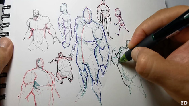
Course Stylized Figure Drawing 21 Draw
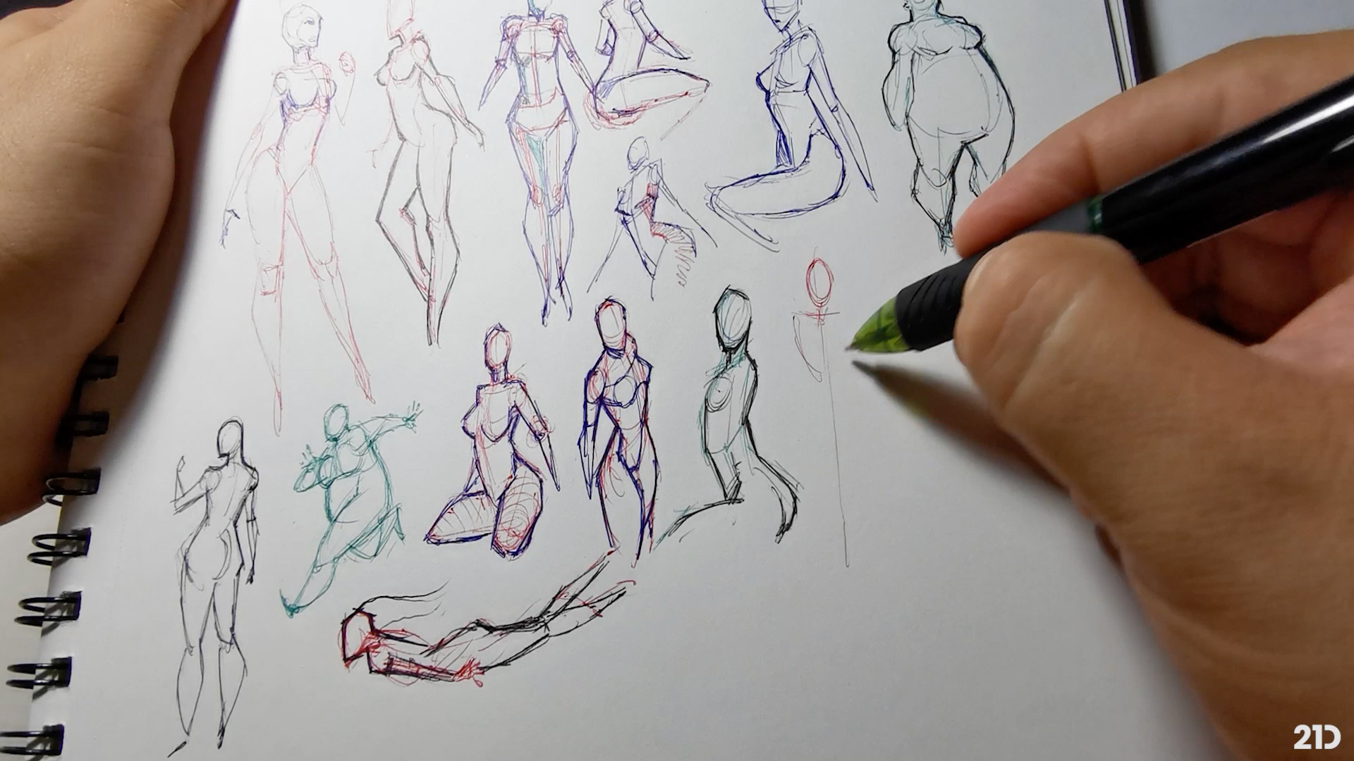
Course Stylized Figure Drawing 21 Draw

Sohranyonnye Fotografii 989 Fotografij Risovanie Zhestami Anatomiya Anatomicheskij Risunok
Anatomy Courses For Artists Best Online Courses To Study Human Anatomy At Home

25 Best Ideas Drawing Figure Tutorial Pose Reference Drawings Figure Drawing Reference Art Reference

Fashion Illustration Portrait Posts 25 Trendy Ideas Drawing Legs Drawing People Figure Drawing
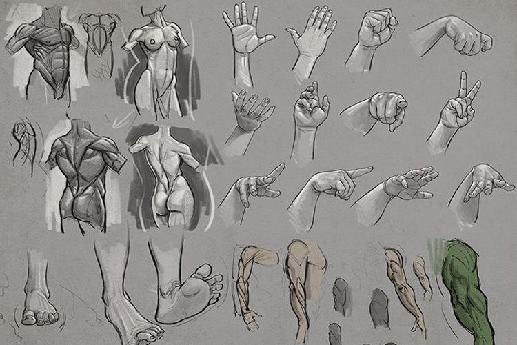
Anatomy Courses For Artists Best Online Courses To Study Human Anatomy At Home

Resultado De Imagem Para Desenho De Tutorial Corpo Malhado Anatomy Art Figure Drawing Art Reference
Course Stylized Figure Drawing 21 Draw

Nephron Diagram How To Draw Nephron Diagram Step By Step For Beginners Biology Diagrams Diagram Art

Image Result For Male And Female Leg Human Anatomy Drawing Anatomy Drawing Body Anatomy

Anatomy Drawing Anatomy Sketches Anatomy Art

Planar Portrait Drawing Examples Doodle Sketch Drawings